
Antennas are probably the most overlooked part of an avionics system, yet they’re among the most important. Except for a few boxes (such as autopilots), avionics rely on antennas to talk with the outside world.
Modern antennas come in many different shapes and sizes. Each antenna is formed by its function. Often, a well-equipped airplane will have an antenna farm on the belly, and it can be confusing to try to figure out what each antenna does. But taken one by one, those antennas are easier to understand. The frequencies at which they operate and their directional qualities usually determine their shape and placement.

Communication antennas
Communication antennas are basic in operation. Each com transmitter has its own antenna, mostly for redundancy. They can be mounted on either the top or bottom of the aircraft, but each installation is susceptible to shadowing from the fuselage. Shadowing is caused by structure, such as the vertical stabilizer or landing gear doors, in the transmitting path of the antenna. Know where your antennas are and how shadowing may affect their range and coverage.
UHF antennas
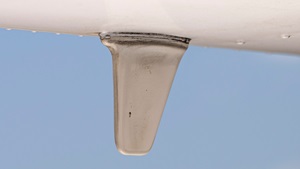
UHF antennas are commonly used for transponders and distance measuring equipment (DME), and they are always found on the bottom of the aircraft. They are about four inches long, and the same antenna can be used for both systems because the transponder frequency is in the middle of the DME frequency band. Two types are commonly used: spike and blade antennas. The spike should only be used for transponders because the antenna length is tuned to one frequency—the transponder frequency. The blade antenna is also called a broadband antenna because it is tuned for a range of DME frequencies. A spike would not work very well for a DME; the blade antennas are preferred because the radiation pattern is better.
The spikes are prone to caking up with oil, reducing the transmitting range. Often, just cleaning a spike antenna doubles your transponder range and gets rid of those intermittent Mode C problems. This goes for all antennas; a dirty antenna does not perform up to its potential. Blade antennas are susceptible to delamination, which tends to detune the frequency response and distort the transmitted signal—that’s why the biennial transponder check is so important.
Nav antennas
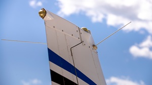
The VHF nav antenna is almost always mounted on the vertical tail, and there are three types: the cat whisker, the dual blade, and the towel bar. The cat whisker consists of a couple of rods jutting out from each side of the vertical stabilizer at a 45-degree angle. But the cat whisker antenna is poor at receiving signals from the side. The dual blade is just that, two blades, one on each side of the tail. The towel bar resembles the common bathroom fixture, one on each side of the tail. The blade and towel bar antennas have equal receiving sensitivity from all directions.
A single nav antenna almost always feeds mulitple nav receivers and sometimes the glideslope as well. Therefore, a failure in the nav antenna system would cause multiple systems to malfunction.

GPS antennas
GPS satellites transmit less than five watts of power, so by the time the signal reaches you, it is very, very weak. Because of this, the GPS antenna has a built-in amplifier to boost the signal for the receiver. Additionally, the GPS frequency is so high (in the gigahertz band) that the signals travel in a line-of-sight manner. This makes receiving the signal susceptible to airframe shadowing, thus mandating that a GPS antenna be mounted at the very top of the fuselage.
Communications radios can cause a lot of interference with GPS, because of the proximity of the panel units or their antennas. Therefore, it is important that the com and GPS antennas be mounted as far apart as possible. Sometimes a com antenna must be relocated to the bottom of the aircraft.
Marker beacon antennas
Marker beacon signals are highly directional, which means you have to be almost directly over the transmitting ground station to receive them; therefore, marker beacon antennas need to be on the bottom of the aircraft. There are a few different types of marker antennas; the more common types look like little canoes about 10 inches long. For some installations, Cessna has used flush antennas that appear to be flat plates under the empennage. It also has used an antenna that consists of a thick wire that protrudes straight down out of the empennage and then makes a turn toward the tail.
Emergency locator transmitter antennas
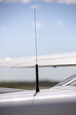
Hopefully, you’ll never have to use an emergency locator transmitter antenna, but in case you do, they are designed to survive an “unscheduled” landing. They are almost always on the upper skin of the empennage and are made of a flexible material. There are a few exceptions, though; some may be buried in the vertical tail or look like small com antennas.
Performance consideration
The physical condition of the antenna plays an important role in its performance. If the antenna is cracked, water may enter and cause delamination (a separation of the composite layers), which may render the antenna useless. And if the antenna base is not structurally strong, the antenna will vibrate from the slipstream and cause the skin to fatigue, eventually causing cracks.
The antenna must be electrically bonded (grounded) to the airframe so a good electrical connection is maintained. If some corrosion gets underneath the antenna, this bond may be compromised and the antenna’s efficiency may degrade. Sealant around the base of the antenna helps to prevent this. Antennas should never be painted over their original coatings; any paint buildup reduces the efficiency of an antenna.
Real estate is very scarce on an aircraft, and sometimes there is very little left for antennas. Every antenna location is a compromise between a solid mounting, shadowing, other antenna interference, ground planes, and aerodynamics.
This text has been adapted from a 2002 AOPA Pilot article written by Paul Novacek.
No comments:
Post a Comment