CFI Instrument Practical Test Standards, FAA-S-8081-9B, April 11, 2021 G1000 - System Block Diagram has 2 GDU 1040 Display Units used for PFD/MFDLRU (Line Replacement Units) – GIA63 – Display GPS Receivers Com/NAV receivers Main System Microprocessors GMA 1347 Audio Control Panel between PFD & MFD Marker Beacon control NAV/COM Digital Audio Intercom Systems ADAHAR - Air Data Attitude Heading Reference System (HA' DA' HAR) Audio panel, central computer process it G1000 Glass Cockpit came out in 2004 Pitot Static System Pitot Tube/Static Source (external thermometer) => Air Data Computer => Primary Flight Display => Air speed, Vertical Speed Indicator, Altimeter, True Airspeed Gyroscopic Instruments (Pitch Bank Yaw) Magnetometer (mag compass) => AHRS (Attitude Heading Reference System => Gyro Equipment => Heading Indicator, Turn Coordinator, Attitude Indicator Air Data Computer Pitot Static Calculate Airspeed/Altitude/Vertical Speed Temp Sensor - Outside Air Temp Pitot Static System remains the same Measure differential pressure from RAM & Static pressure AHRS Attitude Heading Reference System Sense Pitch/Bank/Yaw Magnetometer Accelerometer /Gyroscopic In stead diaphragms and aneroid wafers, the ADAHAR process to display, Altitude, vertical speed and airspeed on PFD. Gyroscopic and Gimbal rings were replaced with magnetometer and accelerometer Turn Coordinator is now: Skip-Skid Indicator (inclinometer) Heading Trend Vector (2 tick marks indicate standard rate turns (magenta line above the HSI) A. Aircraft Flight Instruments and Navigation Equipment
b) Ice may build up on such components as the air scoops, heat or alternate air valves, air intake filters or screens, and protrusions in the carburetor c) Be particularly alert for such icing when flying in snow, sleet, rain, or clouds, especially when ice forms on the windshield or leading edge of the wings and temperatures are near 25°F when super cooled moisture in the air is still in a semi liquid state d) Affects both fuel injected an carbureted engines e) Usually preferable to use carburetor heat or alternate air as an ice prevention means, rather than as a deicer, because fast forming ice which is not immediately recognized may significantly lower the amount of heat available from the carburetor heating system f) Activation of carburetor heat (Cessna TR-182) opens valve allowing hot (but unfiltered) air within engine cowling to bypass air filter and flow directly to turbocharger, carburetor and engine, restoring power.
ii) With carb heat on the fuel-air mixture is enriched (hotter, less dense air) 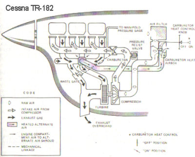
b) Vaporization of fuel plus expansion of air flowing through carburetor causes sudden cooling to freezing temperatures in sometimes less than one second c) Causes drop in RPM and/or manifold pressure (MP) with, usually, rough engine operation d) Cessna TR-182
ii) Suspect if unexplained or exaggerated drop in MP iii) To clear ice References:
The Instrument Flight Manual, Sixth Edition William K. Kershner, 2002 AC20-113 Pilot Precautions and Procedures to be Taken in Preventing Aircraft Reciprocating Engine Induction System and Fuel System Icing Problems AC91-51A Effect of Icing on Aircraft Control and Airplane Deice and Anti-Ice Systems AC91-74 Pilot Guide: Flight in Icing Conditions |
No comments:
Post a Comment