Tuesday, February 27, 2024

6-pack Instruments

The happiest day of your life is when you buy an aeroplane and when you selling it! 


ASI, also shows limiting speeds, horizon, only when up.to speed, no flag, and not toppled if mechanical. 

Altimeter. Barometric height above pilot set ptessure datum, not necessarily sea l.evel 

TS shows Yaw rate, not necessarily turn rate. 

Heading indicator. Only magnetic if slaved to compass or recently synchronised to a mag compass. 

VSI does NOT use pitot input except in sailplanes

Friday, February 23, 2024

DPE - Checkride

 DPE Discussion will certainly help you and your student get ready for their check ride, so come and join us!

We will discuss:

1. Exam Preparation is a must- Paperwork, endorsements, aircraft documentation

2. Organization on the day of the check ride

3. Oral Portion -Aircraft System Knowledge, Inoperative Equipment, weather deciphering the go no go decision making, Setting up your student for success

4. Flight Portion- Maneuvers that are a problem for the applicants, lack of decision making, who is the PIC

5. Safety 

Sunday, February 18, 2024

Power Settings in IFR flying

 SIX CONFIGURATIONS for IFR flying Known power settings help control the airplane while flying IFR


Performance = Power + Pitch

Cruise Level 2400 rpm

Approach Level 2200 rpm/100 kts

Holding Pattern Level 2000 rpm/90 kts

Get out of there (Miss Approach) - Full power /Vy climb

Precision Approach Descent - 1800 rpm/90 kts/500FPM

Non-Precision Approach Descent - 1500 rpm/90 kts/1000FPM


VFR 
Downwind  -  90 Knots, 1st flaps, 1700 rpm
Base   - 80 Knots, 2nd Flaps, 500FPM Descend
Final  - 70 Knots, 30 deg  Flaps


https://www.youtube.com/watch?v=aoa_Vpf4xK4


Wednesday, February 14, 2024

Cessna 172SP Antennas


ANTENNAS - EACH ONE ON YOUR AIRCRAFT HAS A DIFFERENT FUNCTION

Visible on this Cessna 172 are, from left, a communication rado antenna, ELT antenna, GPS antenna, and a second com antenna. Photo by Chris Rose.

Antennas are probably the most overlooked part of an avionics system, yet they’re among the most important. Except for a few boxes (such as autopilots), avionics rely on antennas to talk with the outside world.

Modern antennas come in many different shapes and sizes. Each antenna is formed by its function. Often, a well-equipped airplane will have an antenna farm on the belly, and it can be confusing to try to figure out what each antenna does. But taken one by one, those antennas are easier to understand. The frequencies at which they operate and their directional qualities usually determine their shape and placement.

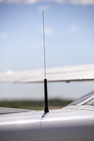
Communication radio antennas usually are mounted on the wings of high-wing airplanes. Photo by Chris Rose.

Communication antennas

Communication antennas are basic in operation. Each com transmitter has its own antenna, mostly for redundancy. They can be mounted on either the top or bottom of the aircraft, but each installation is susceptible to shadowing from the fuselage. Shadowing is caused by structure, such as the vertical stabilizer or landing gear doors, in the transmitting path of the antenna. Know where your antennas are and how shadowing may affect their range and coverage.

Mounted on the aircraf's belly, this transponder antenna also can transmit ADS-B Out signals. Photo by Chris Rose.

UHF antennas

UHF antennas are commonly used for transponders and distance measuring equipment (DME), and they are always found on the bottom of the aircraft. They are about four inches long, and the same antenna can be used for both systems because the transponder frequency is in the middle of the DME frequency band. Two types are commonly used: spike and blade antennas. The spike should only be used for transponders because the antenna length is tuned to one frequency—the transponder frequency. The blade antenna is also called a broadband antenna because it is tuned for a range of DME frequencies. A spike would not work very well for a DME; the blade antennas are preferred because the radiation pattern is better.

The spikes are prone to caking up with oil, reducing the transmitting range. Often, just cleaning a spike antenna doubles your transponder range and gets rid of those intermittent Mode C problems. This goes for all antennas; a dirty antenna does not perform up to its potential. Blade antennas are susceptible to delamination, which tends to detune the frequency response and distort the transmitted signal—that’s why the biennial transponder check is so important.

V-shaped "cat's whiskers" are one type of VHF navigation receiver antenna. All three common types are mounted on the vertical stabilizer. Photo by Chris Rose.

Nav antennas

The VHF nav antenna is almost always mounted on the vertical tail, and there are three types: the cat whisker, the dual blade, and the towel bar. The cat whisker consists of a couple of rods jutting out from each side of the vertical stabilizer at a 45-degree angle. But the cat whisker antenna is poor at receiving signals from the side. The dual blade is just that, two blades, one on each side of the tail. The towel bar resembles the common bathroom fixture, one on each side of the tail. The blade and towel bar antennas have equal receiving sensitivity from all directions.
A single nav antenna almost always feeds mulitple nav receivers and sometimes the glideslope as well. Therefore, a failure in the nav antenna system would cause multiple systems to malfunction.

Two GPS antennas are mounted on top of this fuselage; an antenna for each receiver provides redundancy. Photo by Chris Rose.

GPS antennas

GPS satellites transmit less than five watts of power, so by the time the signal reaches you, it is very, very weak. Because of this, the GPS antenna has a built-in amplifier to boost the signal for the receiver. Additionally, the GPS frequency is so high (in the gigahertz band) that the signals travel in a line-of-sight manner. This makes receiving the signal susceptible to airframe shadowing, thus mandating that a GPS antenna be mounted at the very top of the fuselage.

Communications radios can cause a lot of interference with GPS, because of the proximity of the panel units or their antennas. Therefore, it is important that the com and GPS antennas be mounted as far apart as possible. Sometimes a com antenna must be relocated to the bottom of the aircraft.

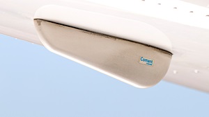
The belly-mounted marker beacon antenna receives signals from a VHF radio beacon that is part of certain instrument approaches. Photo by Chris Rose.

Marker beacon antennas

Marker beacon signals are highly directional, which means you have to be almost directly over the transmitting ground station to receive them; therefore, marker beacon antennas need to be on the bottom of the aircraft. There are a few different types of marker antennas; the more common types look like little canoes about 10 inches long. For some installations, Cessna has used flush antennas that appear to be flat plates under the empennage. It also has used an antenna that consists of a thick wire that protrudes straight down out of the empennage and then makes a turn toward the tail.

When needed, this antenna will transmit signals from the emergency locator transmitter or ELT. Photo by Chris Rose.

Emergency locator transmitter antennas

Hopefully, you’ll never have to use an emergency locator transmitter antenna, but in case you do, they are designed to survive an “unscheduled” landing. They are almost always on the upper skin of the empennage and are made of a flexible material. There are a few exceptions, though; some may be buried in the vertical tail or look like small com antennas.

Performance consideration

The physical condition of the antenna plays an important role in its performance. If the antenna is cracked, water may enter and cause delamination (a separation of the composite layers), which may render the antenna useless. And if the antenna base is not structurally strong, the antenna will vibrate from the slipstream and cause the skin to fatigue, eventually causing cracks.
The antenna must be electrically bonded (grounded) to the airframe so a good electrical connection is maintained. If some corrosion gets underneath the antenna, this bond may be compromised and the antenna’s efficiency may degrade. Sealant around the base of the antenna helps to prevent this. Antennas should never be painted over their original coatings; any paint buildup reduces the efficiency of an antenna.

Real estate is very scarce on an aircraft, and sometimes there is very little left for antennas. Every antenna location is a compromise between a solid mounting, shadowing, other antenna interference, ground planes, and aerodynamics.

This text has been adapted from a 2002 AOPA Pilot article written by Paul Novacek.

Saturday, February 3, 2024

C-R-A-F-T: The Mnemonic for IFR Clearance


Navigating the skies under Instrument Flight Rules (IFR) can be as demanding as it is rewarding, calling for a deep understanding of procedures, clear communication, and a sharp memory. Pilots are often equipped with various tools and techniques to ensure safety and efficiency, and one of the most effective among these is the use of mnemonics.

C-R-A-F-T: The Mnemonic for IFR Clearance

The CRAFT mnemonic stands for:
- Clearance limit: The endpoint of the clearance, which is usually the destination airport.
- Route: The specified path the flight is to follow, which might be altered by Air Traffic Control (ATC) from the initially filed route.
- Altitude: The initial altitude the aircraft is cleared to climb to, along with any expected further clearance for cruise altitude.
- Frequency: The departure frequency the pilots are to communicate on after leaving the airport.
- Transponder: The specific squawk code the aircraft is to use for identification by ATC radar. Additionally, the 'T' can also stand for time, especially concerning a void time, which is a deadline by which the aircraft must be airborne to maintain the clearance validity.

Example of IFR Clearance Using C-R-A-F-T

Let's break down an example:

- Clearance limit: Las Vegas Airport
- Route: HOLTZ seven departure, Daggett transition, then as filed.
- Altitude: Climb and maintain five thousand, with an expectation of flight level three three zero ten minutes after departure.
- Frequency: Departure frequency is 124.50 MHz.
- Transponder: Squawk 6562.

Why Mnemonics Matter
Mnemonics like CRAFT are not just memory aids; they're critical tools that help pilots manage the complex information flow required for safe flight operations under IFR. They ensure that no critical piece of information is overlooked during the critical phases of flight planning and execution.

Final Thoughts...
As we continue to share wisdom and insights into the art of flying, let's remember that good pilots are always learning. The use of mnemonics like CRAFT is just one of the many ways pilots can enhance their safety, efficiency, and confidence in the cockpit. Whether you're flying under the vast blue skies of the United States or navigating the diverse airspace of Europe, the principles of CRAFT ensure that you're equipped with the essential information for a successful flight.

Read Back Script- C-R-A-F-T

Cleared To ________________________
via _______________________________
Climb & Maintain_________________
Expect ___________________
In_____________ mins after Departure
Departure Frequency _______________
Squawk #_________________

Friday, February 2, 2024


Back by Popular Demand

visualisation of the traffic Pattern
over **+100,000 views WOW!
comments and shears on this post
Thank you! Fellow Aviators ๐Ÿ™
Follow & Like Us @iskysthelimit

Read All 15 post on -
“The Art of Perfect Landings” Here @ the Sky’s The Limit and I can promise, that it will help you put all the pieces of the puzzle together, helping you have:
•Faultless,
•Consistent,
•Perfect Landings time and time again...

**This is a Reference to help all levels of Qualified or Student Pilots, on how to better visualise the Traffic Pattern**
- It’s clear to see that without the Adequate...
•Knowledge,
•Training,
•Situational Awareness,
•Airmanship Skills,
•Qualities,

Gained through...
•Good Training
•Listening
•Understanding your CFIs (Certified Flight Instructor)
You will Fall Short of being a...
•Safer,
•Smarter,
• More Confident,
PILOT IN COMMAND!

So INVEST in You’re KNOWLEDGE of FLYING!

Sample Text from The Art of Perfect Landings:

๐Ÿ”‘✈️The Key to Perfect, Consummate, Faultless, Flawless, Consistent Landings is:

๐Ÿ”‘**first Off for you to Gain Consistent & Faultless Landings you must be...

๐Ÿ”‘**Consistent & Flawless with the Whole Pattern / Approach basically the whole Set-up to Land needs to be on Perfect,makes sense right?

So Back 2 Basic Theory Knowledge there Are Four/ or /Five Legs to each Lading Pattern;

✈๐Ÿ”‘️1.Upwind from follow Extended Centreline & Adjust for cross Winds Take Off - 500ft (Flaps Out) (LandingLight Off) (+ev Rate of Climb)(+ev Airspeed) (Vr/Vx/Vy) 300ft Below TPA Make Turn to Cross Wind-

✈๐Ÿ”‘️2.Crosswind - Climbing Turn upto 950ft (Vy/Vx) Remember Speed is King

✈๐Ÿ”‘️3.Downwind - 1000ft (Circuit Height) (Straight & Level) circuit Speed 80kt / Flap Stage 1 (Checklist). *BUMFLICHH*
*Downwind Speed VS-1.5*

✈๐Ÿ”‘️4.Base - 700-500ft Glide Speed / Flaps Stage 2 Descent rate @ 500-600ft / Min Target to be at 500ft on Final.
*Base Speed VSO-1.4*

✈️๐Ÿ”‘5.Final - 500ft- 0ft Full Flaps if Needed/ Flap less approach 1 Stage flaps in strong cross wind gusty condition.
*Final Speed VSO-1.3* GlideSlope- ⚪️๐Ÿ”ด


**Each Turn in the Pattern is @ 90° Turn Left or Right (No more then 30° of Bank) (if it's to the Left we -°Minus to the Right We +°Add ° to our Heading)

For Example:

**#RuleOfThumb L/R Hand Pattern Mind Set:
Left Hand (-°) / Right Hand (+°)

*Left Hand Pattern (-°)Runway#36- 360° X-Wind- 270° D-Wind- 180° Base- 090° Final- 360°

*Right Hand Pattern (+°) Runway#36- 360° X-Wind- 090° D-Wind- 180° Base- 270° Final- 360°

**Pre Landing Checklist Acronym:**
B-rakes - Press Toe-brakes - OFF
U-ndercarriage - Down "Fixed"
M-ixture - "Rich"
F-uel - "ON" & Sufficient for Go-Around
L-ights - "ON" Landing Lights
I-nstruments - Altimeter Set/ D.I / Engine T's & P's in the GREEN
C-arb Heat - Check for ICE & Set Cold
H-atches - Locked & Secured
H-arnesses - ON & Secured

YOUR Flight School & CFI are YOUR KEYS ๐Ÿ”‘ to the SKY...

READ ALL 10 Posts on “THE ART OF PERFECT LANDINGS”

And I’m Confident it will HELP YOU... put all the pieces of the Puzzle Together!!

E-Book PDF downloads available Soon ๐Ÿ”œ
Here @ The Sky's The Limit
The Home of the Safer, Smarter, Confident Pilots.

METAR & TAFs


Meteorological Aerodrome Report (METAR)

Terminal Aerodrome Forecasts (TAF)
METARs & TAF decoder

Meteorological Aerodrome Report (METAR)
A METAR is an observation of current surface weather reported in a standard international format. METARs are issued on a regularly scheduled basis unless significant weather changes have occurred.

METARs typically come from airports or permanent weather observation stations. Reports are generated once an hour or half-hour, but if conditions change significantly (such as rapidly changing weather conditions, aircraft mishaps, or other critical information), a report known as a special (SPECI) may be issued.

*Tempo forecast & Becoming forecast

Tempo - Less the an hour at a time
Becoming - supersedes initial forecast

Terminal Aerodrome Forecasts (TAF)
A TAF is a report established for the five statute mile radius around an airport. TAF reports are usually given for larger airports. Each TAF is valid for a 24 or 30-hour time period and is updated four times a day at 0000Z, 0600Z, 1200Z, and 1800Z. The TAF utilizes the same descriptors and abbreviations as used in the METAR report.

Decoding a METAR & TAF is you’re bread and butter and something you will have to do for every single flight, making sure the weather is suitable and the weather Minima for you’re flight is acceptable is you’re responsibility as acting pilot in command and should be conducted as part of you’re pre flight planning.

The METAR in our example is broken down into 8 informative segments: but usually you can get up to 12 information segments to a Standard METAR - here is a summary of the available information from your typical METAR:-

1. Type of report—there are two types of METAR reports. The first is the routine METAR report that is transmitted on a regular time interval. The second is the aviation selected SPECI. This is a special report that can be given at any time to update the METAR for rapidly changing weather conditions, aircraft mishaps, or other critical information.

2. Station identifier— EGHH, Bournemouth International Airport , four-letter code as established by the International Civil Aviation Organization (ICAO)

3. Date (day) and time of report—27/0420Z Zulu depicted in a six-digit group (270420Z). The first two digits are the date. The last four digits are the time of the METAR/SPECI, which is always given in Coordinated Universal Time (UTC). A “Z” is appended to the end of the time to denote the time is given in Zulu

4. Wind— 210° @ 07 Kt (27007KT) reported with five digits (04009KT) unless the speed is greater than 99 knots, in which case the wind is reported with six digits. The first three digits indicate the direction the true wind is blowing from in tens of degrees. If the wind is variable, it is reported as “VRB.” The last two digits indicate the speed of the wind in knots unless the wind is greater than 99 knots, in which case it is indicated by three digits. If the winds are gusting, the letter “G” follows the wind speed (G26KT). After the letter “G,” the peak gust recorded is provided. If the wind direction varies more than 60° and the wind speed is greater than six knots, a separate group of numbers, separated by a “V,” will indicate the extremes of the wind directions. 00000KT = calm. Wind direction is given in degrees true.

5. Visibility— 6000m- (meters) the prevailing visibility (10 SM) is reported in statute miles as denoted by the letters “SM.” It is reported in both miles and fractions of miles. At times, runway visual range (RVR) is reported following the prevailing visibility. RVR is the distance a pilot can see down the runway in a moving aircraft. When RVR is reported, it is shown with an R, then the runway number followed by a slant, then the visual range in feet. For example, when the RVR is reported as R17L/1400FT, it translates to a visual range of 1,400 feet on runway 17 left. *0000 = 'less than 50 metres' 9999 = 'ten kilometres or more'. No direction is required.

6. Weather—+ = Heavy (well developed in the case of +FC and +PO); - = Light;
no qualifier = Moderate.
BC=Patches DS=Duststorm
FG=Fog GS=Small hail or snow pellets
PL=Ice pellets SA=Sand SQ=Squalls VA=Volcanic ash BL=Blowing DU=Dust FU=Smoke HZ=Haze PO=Dust devils SH=Showers SS=Sandstorm VC=In vicinity
BR=Mist DZ=Drizzle FZ=Freezing
IC=Ice crystals PR=Banks SG=Snow grains TS=Thunderstorm DR=Drifting FC=Funnel cloud GR=Hail (>5mm) MI=Shallow
RA=Rain SN=Snow UP=Unidentified

7. Sky condition—FEW='few' (1-2 oktas), SCT='Scattered' (3-4 oktas), BKN='Broken' (5-7 oktas),OVC='Overcast' Cloud amounts are measured in oktas - one okta = one eighth of cloud cover.
always reported in the sequence of amount, height, and type or indefinite ceiling/height (vertical visibility) (BKN008 OVC012CB, VV003). The heights of the cloud bases are reported with a three-digit number in hundreds of feet AGL. Clouds above 12,000 feet are not detected or reported by an automated station. The types of clouds, specifically towering cumulus (TCU) or cumulonimbus (CB) clouds, are reported with their height. Contractions are used to describe the amount of cloud coverage and obscuring phenomena. The amount of sky coverage is reported in eighths of the sky from horizon to horizon.

8. Temperature and dew point——the air temperature and dew point are always given in degrees Celsius (C) or (18/17). Temperatures below 0 °C are preceded by the letter “M” to indicate minus. If dew point is missing, example would be reported as 18///

9. Altimeter setting—Q1008 ๐Ÿ‡ฌ๐Ÿ‡ง Q indicates the sea level pressure hectopascals. If the letter A is used QNH is in inches and hundredths. ๐Ÿ‡บ๐Ÿ‡ธ reported as inches of mercury ("Hg) in a four-digit number group (A2970). It is always preceded by the letter “A.”

10. Zulu time—a term used in aviation for UTC, which places the entire world on one time standard.

11. Remarks—— the remarks sectional ways begins with the letters “RMK.” Comments may or may not appear in this section of the METAR. The information contained in this section may include wind data, variable visibility, beginning and ending times of particular phenomenon, pressure information, and various other information deemed necessary. An example of a remark regarding weather phenomenon that does not fit in any other category would be: OCNL LTGICCG. This translates as occasional lightning in the clouds and from cloud to ground. Automated stations also use the remarks section to indicate the equipment needs maintenance.

Aviate-Navigate-Communicate


"Aviate-Navigate-Communicate: The Essential Pilot's Mantra ✈️

While it may sound clichรฉd, the wisdom of this mantra stands strong in aviation. In any situation, the order of priorities remains unchanged: first, ensure the aircraft's attitude, power, and drag are properly managed; second, optimize your flight path both laterally and vertically; and finally, once all is in order, engage with ATC.

Never forget to listen to your aircraft; it's been paying attention to you all along. If something doesn't seem right, anticipate challenges, and you'll always stay prepared. There's no need to panic; an airplane won't simply plummet from the sky. If the engine's running, you still have an aircraft, and without it, you've got a glider. Keep flying either as long as you can.

But here's the key: always keep an eye outside the cockpit. Remember those three words even more crucial than 'I Love You': Aviate, Navigate, Communicate. In that precise order.

While addressing any issues inside the cockpit, your primary focus should be on what's happening outside. Keep that aircraft in the air until there's no other choice.

Learn the language of your airplane and have a conversation with it. A well-informed pilot on the ground ensures safe flights in the air, and a pilot who truly understands their aircraft will always be a wise pilot.