Saturday, December 23, 2023

Commercial Maneuvers

The PTS for the Commercial Pilot-Airplane certificate include a number of maneuvers unique to this pilot certificate: 

VFR 

Pre-Flight
ATC/Ground Communication
Taxi (Wind Correction)
Run up - Checks
Take off Roll 
Take off 
4 Fundamentals Straight and level, turns, climbs and descents

Normal Take off 
Normal Landing
Slow Flight
Power on Stall
Power off Stall
Steep Turns
Short field takeoff   (obstacles)
Short field takeoff landing   https://www.youtube.com/watch?v=g-kS8q-vgc8

Soft field takeoff
Soft field takeoff landing 
Regtangular Turn
S-Turn
Spin
Turn about a point
Hood Work - VOR Tracking 
Diversion to alternate airport
Cross Country]
Unusual Attitude
Emergencies - Engine Failures
Emergency Decends
Simulated Engine Failure
Unusual Attitude
Forward slip to Landing
Touch and Go 


** It's OK to discontinue flight if weather is bad ..  Winds heavy gusts.. etc

V Speed    (Velocity speed)

Vr  - Rotate 
Vx  - best Angle of Climb
Vy  - best Rate of Climb
V glide - Best Glide speed 
Vso  - Stall dirty
Vs -Stall Clean
Vs1 
Vfe - Flaps extended 
Vno - max structrual crusing
Vne  - never exceed
Va - maneuver speed


White Arc  40 -85 knots  Vso to Vfe    (Flaps operating Range)
Green Arc   48 - 129 knots Vs1 to Vno
Yellow Arc  129  - 163 KIAS Vno to Vne
Red Line  Vne - 163 KIAS  Max speed

Best Glide - 65 Knots

Fuel Calculation
Wind Speed 

6 Pack


Commercial maneuvers
Chandelles
Lazy Eights
Eights on Pylons
Steep Spirals
Power-off 180-degree Accuracy Approach and Landings. 

Instrument Rating
Rectangular Courses.
Turns Around a Point.
Spin
S-Turns

Approaches

RNP Approach
LNAV LNAV/VNAV, LPAV 
RNAV (GPS) Approach  
DME Localizer Approach
ILS Approach
VOR Approach


GPS Acronyms at a Glance

GPS must be WAAS enable to fly LPV  (more precision)

Minimums and Visibility

APV's (Approach with Verticals)     |    

  • LPV = Localizer Performance with Vertical Guidance  (DA = Decision Altitude lowest amount all)
  • LNAV/VNAV  = Lateral and Vertical Navigation (DA Decision Altitude

  • LNAV  MDA  = Lateral Navigation, Only Lateral Guidance, not Vertical Guidance, Mimimum Decent Altitude (MDA) higher minimims
  • Circuling 


https://www.youtube.com/watch?v=Shp4Dy_1ERY


Clearances
Filing an IFR flight plan
Obtaining a clearance at a towered airport
Obtaining a clearance at a non-towered airport
Obtaining a clearance airborne after departure
Departing VFR on an IFR clearance
Picking up a filed clearance en-route
Obtaining a “Pop-up” IFR clearance


Departures
Departing an airport without IFR procedures
Flying a diverse departure
Flying a textual ODP
Flying a graphical ODP
Getting vectors after takeoff
Using a Visual Climb Over the Airport (VCOA)
Flying a SID
Departing IFR for a climb to VFR-on-Top

En Route
Navigating enroute
Picking a safe cruise altitude
Surviving an unexpected hold
Employing a VFR-on-Top clearance
Requesting a block altitude


Arrivals
Planning and execute a descent
Executing a descent with VNAV
Flying a STAR
Choosing an approach
Selecting the appropriate minimums
Setting up for the approach


Approaches
Flying a visual approach
Flying a charted visual approach
Using a contact approach
Getting vectors to final
Flying a course reversal
Navigating an arc or RF leg
Using a Terminal Arrival Area (TAA)
Following a glidepath/glideslope
Descending with advisory vertical guidance
Descending without vertical guidance
Deciding to continue or miss
Using a Visual Descent Point
Landing straight in
Circling to land
Executing a published missed approach
Executing a missed approach from a circle
Executing an alternate missed approach
Executing a “missed” from below DA/MDA


Unusual Cases
Returning to the departure airport (or a nearby airport)
Flying a dead reckoning segment
Using a Cruise Clearance
Using a Through Clearance
Requesting an approach at one airport to land at another
Using a “Fly Visual” segment
Flying practice approaches under VFR
Flying an ASR/PAR approach


Post Flight
Canceling IFR in flight
Canceling IFR on the ground


Tuesday, December 19, 2023

Instrument Check Ride


  1. 3 types of approaches  LNAV, ILS and VOR
  2. Basic Med (applied)  


Which Three Approaches?

Getting an instrument rating requires a long cross-country with three different approaches. The meaning of “three different approaches” has become a moving target.

Aeronautical experience requirements for the coveted instrument rating include a dual cross country flight. On February 28, 2022, the FAA Chief Counsel rescinded two earlier interpretations regarding the required content of that flight. But the rescission doesn’t end the story or the questions. As of this writing, there is an important question outstanding. We will discuss some thoughts about what we think is likely, but we need to await final word from the FAA.

Three Different Approaches

The requirements for the instrument rating for airplane, helicopter, and powered-lift in 14 CFR § 61.65 include a cross-country training flight. The length of the flight varies for the three ratings (250 NM for airplane and powered lift; 100 NM for helicopters), but each requires an instrument approach at each airport and “Three different kinds of approaches with the use of navigation systems.”

Seems straightforward. However, in March 2008, the FAA Chief Counsel responded to an inquiry from Danny Glaser. Mr. Glaser asked whether an Airport Surveillance Radar (ASR) or Precision Approach Radar (PAR) could be used. The answer was no. The Chief Counsel saw ASR and PAR as radar tracking systems used by controllers to give instructions to pilots, not as “navigation systems” used by aircraft crew.

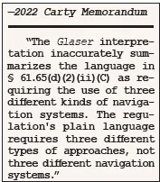
Although this completely answered Mr. Glaser’s question, the interpretation went much further. The author of the Glaser letter added that the three approaches may not simply be “three different kinds of approaches” (the regulatory language) which use some type of navigation systems. Instead, said the Chief Counsel, the approaches “must use three different kinds of navigation systems” (emphasis in the interpretation). The applicant, the Glaser letter went on to say, must choose three different approaches from a short list:

  • Non-directional beacon (NDB)
  • Localizer-type directional aid (LDA)
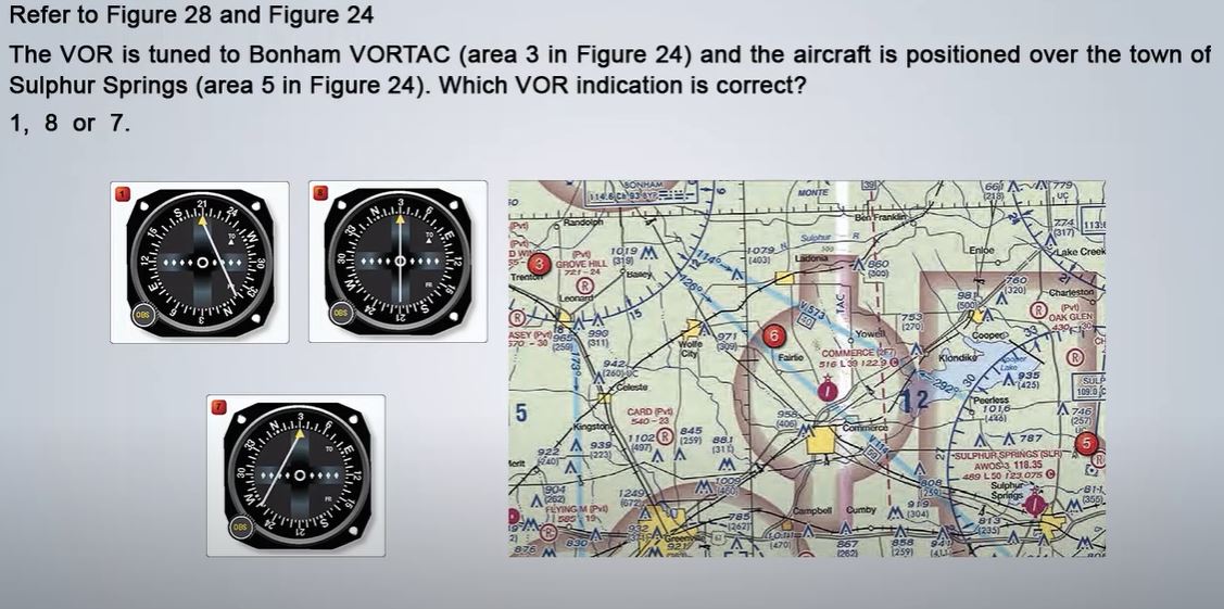
  • Very high frequency omni-range station (VOR)
  • Global Positioning System (GPS)
  • Simplified Direction Facility (SDF)
  • Instrument landing system localizer (LOC)

Intended or not, Glaser led to a very restrictive reading of the cross-country requirement. Many saw it as requiring three different instrument approaches, each of them using a completely different navigation system. An “instrument landing system localizer” is a single “kind of navigation system.” So, flying the full DME arc to track the localizer back course on the final approach course with step-down altitudes to the 600-foot AGL MDA on the LOC BC RWY 17 at College Station, Texas, is arguably the same as receiving vectors to intercept the final approach course and glideslope for the precision ILS RWY 35 at Sugar Land to its 200 and ¾ decision height because they are both localizer-based. Since they do not use different kinds of navigation systems, they cannot be used as two of the three approaches to satisfy the cross-country requirement.

Flight Standards apparently had its own questions about this and requested a clarification. In 2012, the Chief Counsel issued the Pratt letter in an attempt to clarify Glaser. The Pratt letter did nothing to help the situation. It said that the list of specific systems mentioned in Glaser, NDB, LDA, VOR, GPS, SDF, and LOC, “was not intended to exclude navigation systems that might be approved in the future.” What those might be, we still don’t know.

Most importantly, it did not address the problem Glaser created. The closest it came was passing the ball to Flight Standards, saying that branch “is in the best position to issue policy and guidance as to what constitutes the different kinds of approaches allowed.” But Pratt did not disown the controlling interpretation that there must be three different kinds of navigation systems used, restricting what Flight Standards might do. It’s no surprise Flight Standards didn’t run with the ball they were tossed.

Future Navigation Systems

I doubt the writer of Pratt intended to be ironic. When the NAS was filled with VORs, NDBs, SDFs, and other types of ground-based navaids, the restrictiveness of Glaser might not have been a big deal. As of March 2022, there remained almost 1500 VOR approaches but they are becoming less and less common. The number decreases almost every cycle due to a combination of VOR decommissioning through the Minimum Operational Network initiative, the separate program decommissioning “redundant” VOR and NDB approaches, and unrepaired failures.

In comparison, there are only 250 NDB approaches left (many on the chopping block). Even that number is illusory since most modern aircraft lack ADF capability; when someone upgrades their panels, it is often the first thing to go. The others? Well there are 31 LDA approaches, and a single SDF approach, the KMOR SDF RWY 5 in Morriston, Tennessee.

Sadly, with the diminishing number of options, the problem has not been merely academic. The reactions to Glaser restrictiveness have ranged widely. Some see Glaser as answering only the PAR/ASR question and ignore the “different kinds of navigation systems” language as an offhand remark not to be taken seriously.

Others look at the obvious differences between flying ILS and LOC approaches and see the glideslope as a “navigation system” distinction not mentioned in the interpretation. But at the opposite extreme, pilot examiners have been known to reject applicants who did an ILS at one airport and a LOC at another, pointing to the most restrictive interpretation.

Then There’s Carty

As previously mentioned, the 2012 Pratt memorandum passed the ball to Flight Standards to set policy on the acceptability of approaches to meet the requirement. Early in 2021, as the result of a member inquiry, AOPA asked Flight Standards what if anything had been done since then. In May 2021, Flight Standards once again asked the Chief Counsel’s office for reconsideration of Glaser and Pratt. Flight Standards said it “is concerned that the interpretations create requirements that go beyond the language” of the regulation.

This time, in a February 28, 2022 memorandum to Robert C. Carty, the Acting Executive Director of Flight Standards, the Chief Counsel’s office rescinded both Glaser and Pratt. The memorandum includes a legal-style analysis that looks at regulatory definitions and the treatment of different tasks in the Instrument ACS, but the bottom line is that the 
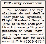
regulation requires “three different kinds of approaches,” not “three different kinds of navigation systems.” In a full reversal of Glaser and Pratt, the Carty memo also says that PAR and ASR are indeed “navigation systems” and nothing regulatory prevents their use to meet the IFR cross-country requirement.

The Rest of the Story

An important question remains. What approaches do qualify as three different types? Carty leaves the answer to Flight Standards. The full and complete abandonment of the Glaser and Pratt analysis leaves Flight Standards able to make policy to fit the realities of today’s environment and to adjust for tomorrow’s without the straight jacket of legal limitations.

As of this writing, Flight Standards has not acted officially. However, they have not been idle. Personnel at Flight Standards’ General Aviation & Commercial Division Training and Certification Group (AFS 810) have received and responded to several questions about which approaches count. A draft revision to Chapter 5 of the Flight Standards Information Management System (Order 8900.1 also known as FSIMS), has been written and is in the queue for approval.

Order 8900.1 guides aviation safety inspectors in performing their jobs. Chapter 5 deals with Airman Certification. While nothing is final until the proverbial (or virtual) ink is dry, informal responses to inquiries suggest Flight Standards is well aware of the rise of Performance Based Navigation and the reduced use of ground based navaids, and is prepared to take a reasonable and practical approach.

If I were to write my own ending, it would differentiate approaches based on the navigations sources used and whether the approach is flown with or without official vertical guidance. An ILS or LPV DA with a TERPS-vetted glidepath is official; “+V” advisory guidance to a VNAV or VOR MDA is not. So an ILS would be different from a localizer-only approach. PAR approaches (precision) would be treated as a different kind of approach from ASR (non-precision).

Perhaps vectors to the final approach course would be treated as different from a full approach using a course reversal or Terminal Arrival Area. In the best ending of all, RNAV approaches to LNAV, LP, and LPV minima would be different from each other, solving the potential problem of aircraft whose owners upgraded to GPS-only units like Garmin’s GPS 175 and GNX375 and choose to have no VOR or localizer receiver.


Monday, December 11, 2023

6-Pack Instruments

6 Pack Instrumentation 

                    (ASI) Airspeed Indicator     (Ai) Attitude Indicator    (ALT) Altimeter

                    (TC) Turn Coordinator        (Hi) Heading Indicator    (VSI)  Vertical Speed Indicator 


Pitot/Static Instruments - 
(ASI) Airspeed Indicator 
(ALT) Altimeter
(VSI)  Vertical Speed Indicator 

GyroScopic Instrument (Vacuum) Rigidity in space  
(Ai) Attitude Indicator   (Artificial Horizon)
(Hi) Heading Indicator    (Directional Gyro - DG)

GyroScopic Instrument (Electrical)
(TC) Turn Coordinator    (Slip Indicator, "Needle and Ball," Turn and Bank,  


Engine Instruments: Chronometer/OAT/Voltmeter - LCD Display left of ASI, Fuel Flow and EGT - dual analog display left of turn co-ordinator, Fuel Quantity Indicators - Not Shown, left of previous, Suction Pressure and Ammeter - not shown, below Fuel Flow & EGT, Oil Temperature and Pressure - not shown, left of previous. Below: Mageto Selector - key switch left of Master Switch Master Switch - red double switch. Controls entire electrical system. Fuel Pump, Lights, and Pitot Heat - toggle switches between Master and Avionics. Avionics Switch - White Double Switch. Controls incidental electronics. Right of 6-pack: ILS/LPV/VOR1 Indicator - cross-shaped indicator right of altimeter. VOR2 Indicator - Backup VOR Indicator, or used to determine airway intersection under IFR. PA Control and OMI beacons - top panel of radio system. Controls the volume of passenger mics and outdated marker beacon technology. GPS - Self Explanatory, large screen. Primary/Secondary Radios - self explatory. Below the GPS. Transponder - below both radios, used to determine location of ATC Radar. Centre Pedestal: Interior Lights - the 2 twist knobs left of the Throttle. Used for night flying. Alternate Static Source - Red know between and below throttle and mixture. Used in case of static source blockage/failure. Fuel Shutoff Valve - Self Explanatory, just above fuel selector. Cabin Air/Heat - pull knobs below co-pilot yoke. Environment control.


6 - Pack Altimeter

 VFR Day Equipment Requirements FAR 91.205


ATOMATO FLAMES

  • Airspeed
  • Tacometer (for each engine)
  • Oil Pressure Gauge (for each Engine)
  • MAgnetic Direction Indicatior
  • Altimeter 
  • Temperature Gague (for each liquid cooled engine)
  • Oil Temperatue Gague (for each air cooled engine)
  • Fuel Gague (for each tank)
  • Landing Gear Position Indicator
  • AntiCollision Light
  • MAnifold Pressure Gague (For Each Altitude Engine)
  • ELT
  • SeatBelts for each occupant


Altimeter

Types of Altitude

Indicated Altitude 
- Whatever the Altimeter is reading (regardless of what the altimeter is set at) 
- eg 625' MSL (Mean Sea Level) Not always accurate

True Altitude 
- Real Altitude
- True Altitude Above Sea Level
- Hight Above Sea Level Expressed in MSL 

Absolute Altitude
- Hight above Surface (Ground)
- Expressed in AGL (Above Ground Level)

Pressure Altitude
- Standard Datum Plane (29.92" Hg)
- if Kelsi meter is adjuster to 29.29"HG you reading is hight about standard datum plane

Density Altitude
- Pressure Altitude Corrected for non-standard temperature 
- The 4 H's - Hight, Hot, Heavy (Weight), Humid  - Aircraft performance could suffer
- Density Altitude is Pressure Altitude and Temperature this is how aircraft performance is calculated


True: Actual height above sea level.
Indicated: What’s read on the instrument.
Absolute: Height above ground level (agl).
Pressure: What’s read on the instrument with the pressure set to standard (29.92 inches).
Density: Pressure altitude corrected for nonstandard temperature (what the aircraft thinks the altitude is).


Altimeter Error 

- Calibrated at 15Deg C (59 Def F)
- Higher than 15C = Higher than you think
- Lower than 15C = Lower than you think
- AIM 7-3-1 (Table  Temp vs Hight Above Airport In Feet)

- High to Low .. Look out below (from a airport with higher barometric pressure to an airport with lower barometric pressure, look out below meaning the airport hight is lower that altimeter indicated if the Altimeter is not adjusted to the lower barometric pressure)

- From low to high - High in the Sky


  • If your true Altitude might stay the same, the absolute altitude may change with the turaine
  • you can subtract the True Altitude from Ground Elevation


Reference

https://www.youtube.com/watch?v=q27N5EFWmpM


Saturday, December 9, 2023

Density Altitude

Density Altitude


Cold Dry Air  is MORE Dense - Provide MORE power trust and lift

Hot Humid Air is LESS Dense - Provide LESS power thrust and lift


Density Altitude is where the Aircraft Performance is Calculate


Hot and Humid Day /High Density Altitude - Aircraft Behaves as it is at a higher than true Altitude

True Altitude 

Cold and Dry Day/ Lowe Density Altitude - Air Craft Behaves as it is at a lower than True Altitude


Low Density Altitude 

Denser Air/More Performance/ Shorter take off Roll /Highter Climb Rate


High Density Altitude 

Thinner Air/Less Performance/ Longer Take off Roll / Lower Climb Rate

Tuesday, October 24, 2023

VFR Clearance Class C airport


VFR Clearance Class C

Pilot: Good After Ashiville Ground, Cessna 234YC, VFR Clearance, to LZU at 4500

Ground: 

Squack: 124.2
Heading: 
Departure Frequency: 126.56


https://www.youtube.com/shorts/K2nqW9SY-L8

Thursday, September 21, 2023

VOR

 Heading and Bearing


Answer South


VOR operates from 108.0 to 117.95  just above the frequency range of an FM radio. 

Tune in the Frequency of  Grand Canyon VOR 1119.0MHz on nav Radio
Listen to morse code and validate it
turn obs knob until yuo have FROM Flag, and then center the needle.
Report to Instructor "we are on the RADIAL 310 FROM Grand Canyon VOR"


Correct with Bracketing  eg 20 deg to left or right and when intercept then decrease turn by 1/2 of 20 deg or 10 deg

Receiver operates in enroute, Terminal and approach modes and full deflection of needle changes in each mode. 

Beyond 30 miles Enroute Mode   10 nautical miles (full deflection is 5Nautical Miles
Within 30 miles of departure /or arrival it works in Terminal Mode  10 nautical miles (full deflection is 5Nautical Miles
Approach Mode - 5 nautical miles. 


Draw a straight line from VOR on 310 RADIAL on Sectional Chart
Check your DME say 25 Nautical Miles from Grand Canyon VOR  
Draw a 25 Nautical Mile Circle
BOOM you are there!!


Instructor: Fly us from present position to Peach Spring VOR
Student:  Tune in to the Peach Spring VOR 112.0MHz
Turn the OBS knob until you have a TO Flag indication
Center the Needle
Turn the aircraft to the Heading 190 as shown on VOR
Ignore Winds for a Second


If you are flying FORM the station or away from the VOR, you are flying on a RADIAL  (radials radiates from the station)

If you are flying TO the station or towards the VOR, you are flying a Course TO the Station, or Inbound Radian, (the CDI is a COURSE Deviation Indicator)  on a Bearing 

  • Radial From VOR 
  • Fly TO VOR
  • Wind Correction - Angle 


F - Find Frequency (from Sectional etc)
E - Enter Frequency (On NAV)
A - Activate  (Make Frequency active on NAV radio)
V - Verify  - (Verify Morse Code)
S - Select VOR (fly to VOR)


What is a VOR?
VOR = Very High Frequency Omnidirectional Range Station (VOR)
Oriented to Magnetic North

What are the Components of VOR
Radio Navigation Aid  -  Antenna, Receiver, VOR Indicator

Principle of Operation of VOR

1. Ground Station Send out directional signal 360 deg 30 times every second
2. A second reference signal is send out everytime the the rotating signal passes 360 degrees

3. Aircraft VOR compairs the 2 signals and uses the difference of the 2 signal to calculate  the Bearing or Radial the aircraft is FROM the VOR station

4. The VOR reciever and use the signal to indicate the bearing TO the station.


VOR help determine your bearing TO or FROM a Station but not do not give you any indication on which DIRECTION your aircrat is Pointing.

VOR Indicator in the aircaft has 4 parts : 
1. Course Index (N E S W)
2. OBS Knob
3. Course Deviation Indication Needle
4. TO/FROM Indicator


The spinner  Tail = TO; Center = VOR; Head = From


If you want to fly TO the station


  1. Turn the OBS Knob until you have a TO indication and the Course Deviation Indication Needle is Centered.
  2. Turn your aircraft unit it is pointing to the same direction show by the VOR Course Index.
  3. As long as the Heading Indicatior and the Course Index agree AND you keep the Needle center, you will fly right to the VOR station.
  4. When you pass the station, the TO flag will flip to FROM


How to Read VOR to know where the aircraft is located. 

Example 1
Given Info on VOR 

1. Course Deviation Needle is deflected to Right
 - Aircraft is on the Left (shaded in Yellow)

2. TO Flag is showing
- Aircraft is on the TAIL side of the Radial

This means the aircraft is on the botton left quadrant

3. Course Index is 21 =210 deg
We need to turn the diagram so that it aligns with the 210 as it is indicated with the Course Index 


Rotate to match Course Index  210 deg
- which means the aircraft is somewhere EAST of VOR


Example 2
Given Info on VOR 

1. Course Deviation Needle is Center
 - Aircraft is on the RADIAL however which side?  (shaded in Yellow)

2.  FROM  Flag is showing
- Aircraft is on the Radial Side HEAD side of the Radial

This means the aircraft is on the TOP half of the Radial

3. Course Index is 21 =210 deg
We need to turn the diagram so that it aligns with the 210 as it is indicated with the Course Index 


Have to Rotate the Radial so that it matches the Course Index of 210 deg
- Which means the airplane is in the South-SouthWest of the VOR


Bearing is my position in relationship to something else. It does not care what heading you are flying.  It is the course you need to fly to the station. It is the course to the VOR Station.


When the Course Deviation Needle touches the outer ring of circle, you stop the turn and straighten out the aircraft at 300 deg.  


VOR ONLY give BEARING TO or FROM a STATION. 

They DO NOT have ANYTHING to do with HEADING! 


VOR VHF (Very High Frequency) Omni-Directional Range  => NAVAID RADIO in Aircraft.

Tune VOR frequency on Navaid Radio

Switch to Active  = Listen to 


VOR ONLY give BEARING TO or FROM a STATION. 

They DO NOT have ANYTHING to do with HEADING! 


VOR VHF (Very High Frequency) Omni-Directional Range  => NAVAID RADIO in Aircraft.

Tune VOR frequency 117.9 on Navaid Radio

Switch to Active  = Listen to 


https://www.youtube.com/watch?v=6S95qXQNTzM&t=20s